
As in all major manufacturing industries worldwide, this also applies to the cement industry. The emission of hazardous substances and environmental pollution should be reduced or prevented in any possible way. To effectively support climate protection, to maintain and restore a clean environment are the most important goals of modern cement producers. The motivations are manifold. Be it due to new environmental legislation, pressure from the local population, external organizations and interest groups of the company or self-imposed sustainability obligations.
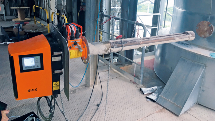
Figure 1: GM32 on site during preventive check-up
NOx emissions and regulations
Nitrogen oxides (NOx) and other nitrogen compounds arising from cement production are considered the main reason for photochemical smog and formation of nitric acid and acid rain. They are formed either by a combination of fuel-based nitrogen with oxygen within the flame or by a combination of atmospheric nitrogen in the combustion air. The two main mechanisms for the production of NOx in a clinker burning process are the reaction of nitrogen in combustion air at high temperatures (thermal NOx) and the combustion of nitrogen containing fuels (fuel NOx).
Globally the emission limits for NOx show the same trend towards lower emission standards and stricter penalties for non-complying plants. However, there are still big differences for this pollutant. Most national limits are in the region of 500 to 1,000 mg/Nm3. Some plants in the EU take pioneering roles by having fixed emission limit values of down to 200 mg/Nm³, depending on which kiln process is applied and what type of fuels are being used.
Even though primary measures such as flame cooling, installation of low-NOx burners, staged combustion and general process optimizations show significant effects in reducing NOx emissions, secondary measures are seen as vital for NOx abatement and lower emission limit values. In cement production two secondary measures, selective catalytic reduction (SCR) and selective non-catalytic reduction systems (SNCR), have constantly gained in popularity over the last years and are accepted and proven technologies when controlled in a proper way.
SCR and SNCR – two technologies, one goal
SCR and SNCR denitrification (DeNOx) plants use ammonia (NH3) for an efficient reduction of NOx to form the harmless nitrogen and water. The main difference between both technologies is the use of a catalyst. The SNCR, i.e. DeNOx without a catalyst, is installed in the riser duct or calciner after the rotary kiln at a temperature range of 900 to 1.000 °C. Depending on the type of the SCR it can be placed in the high dust raw gas stream (e.g. directly after the pre-heater) or before the main stack in the low dust gas stream as a so-called tail-end or low-dust SCR. A SCR consists of a specific number of catalyst layers and operates at gas temperature of around 300 to 350 °C. The reducing agent, typically ammonia water or urea, is injected at the SCR inlet.
For an initial reduction of NOx emission values, often a SNCR is sufficient and lower in cost to install than a SCR. An efficient reaction between the NH3 and NOx depends highly on the temperature. At temperatures greater than 1.200 °C, NH3 converts to NOx, at temperatures lower than 800 °C, the ammonia slip increases. Thus, an efficient and well-adjusted control of the ammonia injection is of high importance for the compliance of gas emission limits when using a SNCR. The presence of the catalyst in the SCR allows the operation at lower temperatures and offers a higher stoichiometric ratio, which leads to a lower amount of injected reducing agent and ensures a lower NH3 slip. Thus, very low NH3 and NOx emission limit values can be adhered to.
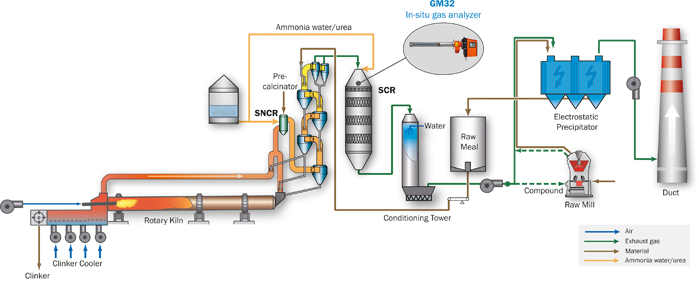
Figure 2: Cement diagram to illustrate the production and gas flow and identifying the measuring point
GM32 – the innovative in-situ gas analyzer
The in-situ gas analyzer GM32 from SICK measures simultaneously up to four components (NO, NO2, NH3, SO2) plus temperature and pressure directly inside the process gas stream. The direct measurement inside the duct (in-situ) leads to fast measuring results due to a short response time, which is perfectly suitable for process control. The GM32 analyzer unit is equipped with a gas permeable probe (GPP), which is positioned inside the duct (see fig. 4). Using the wavelength-specific light absorption by the gas mixture on the active measuring path, the sender/receiver unit determines the concentration of the gas components present. UV light sent from the sender/receiver unit passes the active measuring path of the GPP probe and is reflected by a triple reflector at the end of the probe. The permeable filter element — the heart of the GPP— keeps all dust outside of the measuring path, where the light passes through, while the gas permeates quickly through the pores ensuring the required fast response time. The GM32 uses the DOAS principle (Differential Optical Absorption Spectroscopy) where the absorption lines of specific gases in a particular wavelength range are evaluated.
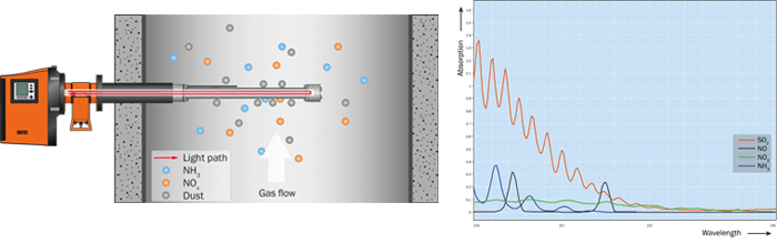
Figure 3: GM32 measurement technology: optical path and UV absorption spectra
Neither the filter, nor the rest of the gas analyzer require weekly or monthly checking, cleaning or other high frequent maintenance work
Due to the higher temperature and possible temperature fluctuations at the measuring location, stack movements are possible. With the implemented auto alignment correction, which aligns the light beam continuously during operation, stack movements as well as vibrations can be compensated for. This ensures a stable and reliable measurement.
In comparison to many other measuring systems, which require a frequent test gas calibration, the integrated filters for zero and span check (approved according to EN15267) automatically compensate drifts and ensure a correct and accurate measurement. This helps in addition to keep operational expenditures very low.


