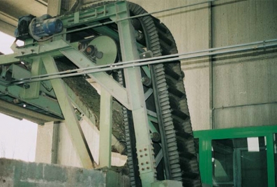
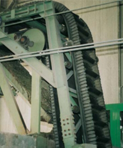
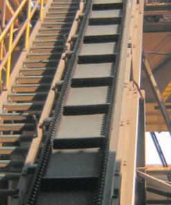
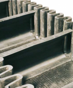
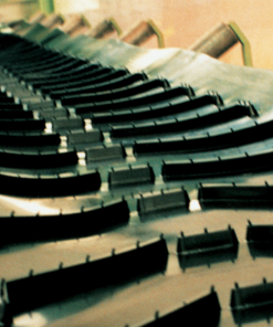
Sidewalls
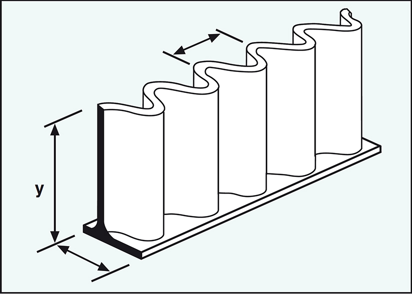
DIMENSIONS approx. (mm)
| TYPE | Width W |
Height H |
Pitch p |
| 40/30 | 30 | 40 | 25 |
| 40/50 | 50 | 40 | 50 |
| 60/50 | 50 | 60 | 50 |
| 80/50 | 50 | 80 | 50 |
| 100/50 | 50 | 100 | 50 |
| 120/50 | 50 | 120 | 50 |
| 160/70 | 70 | 160 | 55 |
| 200/80 | 80 | 200 | 65 |
| 200/75 | 75 | 200 | 60 |
| 240/80 | 80 | 240 | 65 |
| 240/75 | 75 | 240 | 60 |
| 250/75 | 75 | 250 | 60 |
| 280/75 | 75 | 280 | 60 |
| 300/100 | 100 | 300 | 85 |
| 300/75 | 75 | 300 | 60 |
| 400/100 | 100 | 400 | 83 |
| 500/100 | 100 | 500 | 83 |
| 600/100 | 100 | 600 | 83 |
| 630/100 | 100 | 630 | 83 |
CLEATS
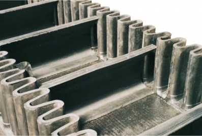
Kích thước xấp xỉ. (mm)
| TYPE | Width mm W |
Height mm H |
| D55 | 80 | 55 |
| D75 | 100 | 75 |
| D90 | 110 | 90 |
| D110 | 110 | 110 |
| D140 | 150 | 140 |
| D180 | 150 | 180 |
| N55 | 90 | 55 |
| N75 | 90 | 75 |
| N110 | 110 | 110 |
| C70 | 70 | 70 |
| C90 | 110 | 90 |
| C110 | 110 | 110 |
| C140 | 140 | 140 |
| C180 | 170 | 180 |
| C220 | 175 | 220 |
| C230 | 175 | 230 |
| C240 | 175 | 240 |
| U180 | 228 | 180 |
| U220 | 228 | 220 |
| U280 | 228 | 280 |
| U360 | 228 | 360 |
| U380 | 228 | 380 |
| U480 | 228 | 480 |
| U580 | 228 | 580 |
| U600 | 228 | 600 |
Cleats and sidewalls dimensions are only approximate
For different typologies, please ask our commercial dept

Base belt – The cross stabilized construction
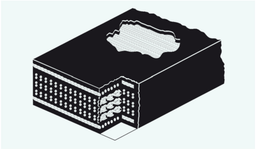
The main required characteristic of a base belt suitable for Flexobord applications is the controlled transversal stiffness, also named cross stabilized construction.
The following sketches indicate the consequences due to a wrong choice of the base belt:

Standard base belt without any particular transversal stiffness are usable only for horizontal flat belts made with only corrugated sidewalls without transversal cleats.
According to the heaviness of the application, the following base belt typologies are available:
- XR Composed by only textile fabrics with high transversal stiffness; two special synthetic layers assure the correct cross stabilizing properties. They are provided with cut edges for light and medium applications.
- This base construction can be sold as indipendent product with the brand name TEXRIGID®. The sketch on the right shows the cross stabilized construction.
.
|
Belt width |
TEXRIGID® styles (kN/m) Standard covers 5+3 MM |
||||
| 500/3+2 | 630/4+2 | 800/5+2 | 1000/5+2 |
1250/5+2 |
|
| RECOMMENDED BELT WIDTHS (mm) | |||||
| 400 | x | ||||
| 500 | x | x | |||
| 600 | x | x | x | X | x |
| 650 | x | x | x | X | x |
| 800 | x | x | X | x | |
| 1000 | x | x | X | x | |
| 1200 | x | X | x | ||
| MINIMUM SUGGESTED PULLEY DIAMETER (mm) | |||||
| Drive | 500 | 630 | 630 | 800 | 1000 |
| Return | 400 | 500 | 500 | 630 | 800 |
| Snub | 315 | 400 | 400 | 500 | 630 |
Standard production length: 200 m;
Typical production widths as slab: 1200, 1300 and 1600 mm
Unless specifically designed, TEXRIGID are not suitable for sealing applications.
SR Composed by a mix of multi-ply synthetic carcass and suitable steel reinforcement to ensure high transversal stiffness for any kind of Fleobord applications, up to the heaviest.
They are provided only with moulded edges.
This cross stabilized base belt can be sold as indipendent product with the brand name CROSSRIGID®.
The sketch on the left shows the cross stabilized construction.
|
Belt width |
CROSSRIGID® styles (kN/m) Standard covers 5+3 MM |
||||||
| 500/3 | 630/4 | 800/4 | 1000/5 |
1250/5 |
|||
| INDICATIVE BELT THICKNESS (mm) | |||||||
| 800 | 14,0 | 15,0 | 16,0 | – | – | ||
| 1000 | 14,0 | 15,0 | 16,0 | 17,5 | 18,5 | ||
| 1200 | 15,0 | 16,0 | 17,0 | 18,5 | 19,5 | ||
| 1400 | 16,5 | 17,0 | 18,0 | 19,5 | 20,5 | ||
| 1600 | 17,0 | 18,0 | 19,0 | 20,5 | 21,5 | ||
| 1800 | 19,0 | 20,0 | 20,5 | 22,0 | 23,5 | ||
| MINIMUM SUGGESTED PULLEY DIAMETER (mm) | |||||||
| Drive | 400 | 500 | 630 | 800 | 1000 | ||
| Return | 315 | 400 | 500 | 630 | 800 | ||
| Snub | 250 | 315 | 400 | 500 | 630 | ||
Standard production length: 200 m;
- The transversal stiffness of CROSSRIGID is not suitable for sealing applications unless supported over the whole belt width with a suitable rigid structure; specific constructions are necessary for these special products to assure the static stability when rest only along the edges: SIG SpA designs and produces such a products with the brand name SEALTEX.
- ST Designed for the heaviest applications where high elevation and/or conveying capacity are involved, it is composed by longitudinal steel cords with a special transversal steel reinforcement to assure the required stiffness. Full range is available from 1250 to 3500 KN/m; for the correct belt selection, please contact our technical dept.
COVER SELECTION
- Base belt can be provided with alternative rubber covers with reference to the specific application. On request, special productions with cleats and edges of the same rubber of base belt can be realized; please ask our sales dept to verify all details.
- CL: Standard abrasion resistant
- EC: Extra abrasion and tear resistant
- OM: Vegetable oil and animal greases resistant
- OH: Mineral oil resistant
- BS: Self-extinguish and antistatic
- AG: Vegetable oil and animal greases resistant, self-extinguish and antistatic
- CX: Heat resistant up to 130 °C with peaks of 150 °C
Elements for plan Design
MINIMUM SUGGESTED PULLEY DIAMETERS (mm)
| SIDEWALL TYPE |
DRIVE PULLEY |
TAKE-UP PULLEY |
DEFLECTION WHEEL |
| 40/30 | 125 | 125 | 160 |
| 40/50 | 125 | 125 | 160 |
| 60/50 | 200 | 200 | 250 |
| 80/50 | 200 | 200 | 250 |
| 100/50 | 315 | 315 | 400 |
| 120/50 | 400 | 400 | 500 |
| 160/70 | 500 | 500 | 630 |
| 200/80 | 630 | 630 | 800 |
| 200/75 | 630 | 630 | 800 |
| 240/80 | 800 | 800 | 1000 |
| 240/75 | 800 | 800 | 1000 |
| 250/75 | 800 | 800 | 1000 |
| 280/75 | 1000 | 1000 | 1200 |
| 300/100 | 1000 | 1000 | 1200 |
| 300/75 | 1000 | 1000 | 1200 |
| 400/100 | 1250 | 1250 | 1600 |
| 500/100 | 1600 | 1600 | 2000 |
| 600/100 | 2000 | 2000 | 2500 |
| 630/100 | 2000 | 2000 | 2500 |
DEFLECTION WHEELS
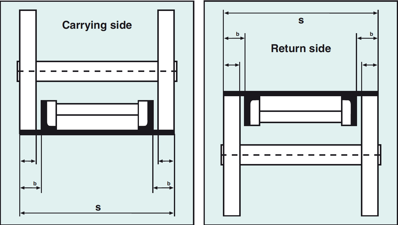
FREE LATERAL SPACE WIDTH (mm)
| Belt width B (mm) |
400 | 500 | 650 | 800 | 1000 | 1200 | 1400 | 1600 | 1800 | 2000 |
| Free lateral space b2 (mm) |
60 | 60 | 75 | 100 | 125 | 150 | 175 | 200 | 225 | 250 |
| Wheel min width (mm) |
48 | 48 | 60 | 80 | 100 | 120 | 140 | 160 | 185 | 210 |
OTHER USEFULL INFORMATIONS for PLANT DESIGN
- Minimum cleat pitch = 1,5 x Max lump size
- Minimum cleat height = (1,5 to 2) x Max lump size
- Width of support idlers (mm) = Belt width (mm) + 100 mm
- Idler pitch – carrying side ≤ 1 m max
- Pitch of full width return idlers ≤ 2 m
- Pitch of short return idlers ≤ 1 m
- Lateral idlers for alignment: min 4 for each straigth section; max distance = 12 m
