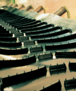
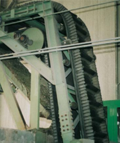
Technical Characteristics
STANDARD PRODUCTION PROGRAM
|
Belt style N/mm |
Max working tension
Vulcanized N/mm |
Max working tension
Mechanical N/mm |
Cover mm |
Total mm |
Total kg/m2 |
|
400/1 |
50 | 40 | 5+2 | 9.0 |
11.0 |
|
630/1 |
80 | 63 | 6+3 | 12.0 | 14.5 |
|
800/1 |
100 | 80 | 6+3 | 12.5 | 15.0 |
|
1000/1 |
125 | 100 | 6+3 | 13.0 | 15.5 |
|
800/2 |
80 | 63 | 6+3 | 14.0 |
17.0 |
| 1250/2 | 125 | 100 | 6+3 | 16.0 |
19.0 |
| 1600/2 | 160 | 125 | 6+3 | 17.0 |
20.5 |
| 2000/2 | 200 | 160 | 6+3 | 18.0 |
21.5 |
For different belt styles and cover thickness, please do not hesitate to contact our commercial dept.
MINIMUM RECOMMENDED PULLEYS DIAMETERS mm
| % RMBT | |||||||||
|
60% ÷ 100% |
30% ÷ 60% | ≤ 30% | |||||||
|
Belt style N/mm |
A | B | C | A | B | C | A | B | C |
| 400/1 | 315 | 250 | 200 | 250 | 200 | 160 | 200 | 200 |
160 |
|
630/1 |
400 | 315 | 250 | 315 | 250 | 200 | 250 | 200 | 160 |
| 800/1 | 500 | 400 | 315 | 400 | 315 | 250 | 315 | 250 |
200 |
|
1000/1 |
630 | 500 | 400 | 500 | 400 | 315 | 400 | 315 | 250 |
|
800/2 |
800 | 630 | 500 | 630 | 500 | 400 | 500 | 400 | 315 |
| 1250/2 | 1000 | 800 | 630 | 800 | 630 | 500 | 630 | 500 |
400 |
| 1600/2 | 1250 | 1000 | 800 | 1000 | 800 | 630 | 800 | 630 |
500 |
| 2000/2 | 1250 | 1000 | 800 | 1250 | 1000 | 800 | 1000 | 800 |
630 |
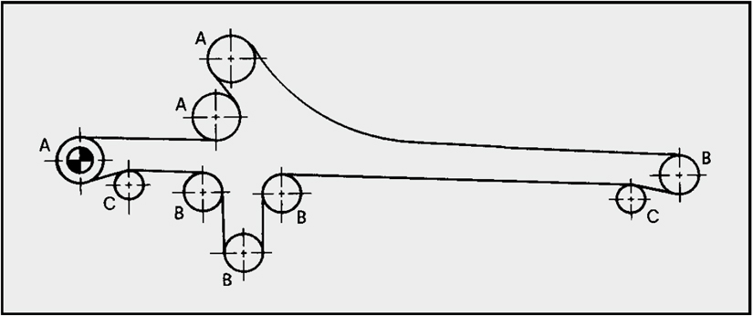
A: drive and tripper pulleys
B: tail, take-up and low tension pulleys
C: snub pulleys (max angle 30°)
% RMBT: % of Recommended Max Belt Tension
Comparative Graphics
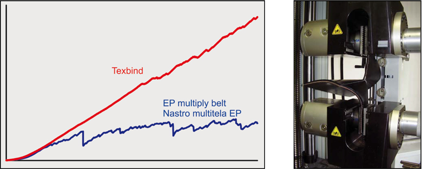
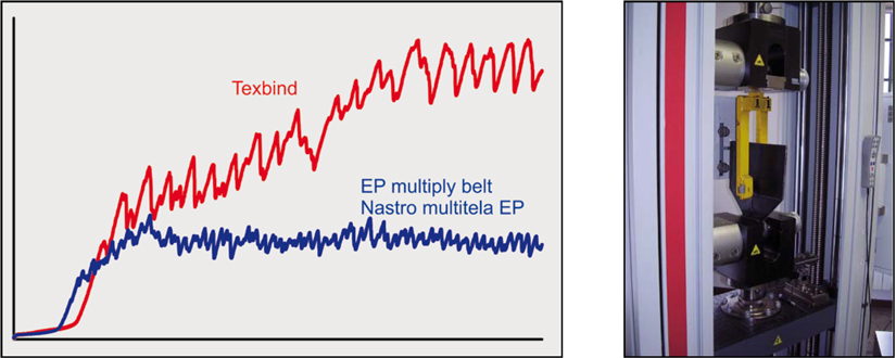
- The great advantages that Texbind belts show in the heaviest and strongest applications are much more evident during instrumental laboratory verifications.
- Graphics here below refer to destructive tests of cutting and tearing, realized in the SIG SpA technology laboratory according to the international standards.
- Both the procedures highlight how the Texbind resistance continuously increases during the test while for standard EP multiply belts the tendency is indented.
- This is due to the fact that the weftyarns of Texbind belts, free to move inside the straight warp fabric, go close one to the other multiplying the single resistant strengths, already high themselves; on the contrary, this is not possible for EP belts where weft yarns tend to break singularly just because binded in the woven structure of the fabric.
- Cutting resistance test
Splicing Procedure
- Texbind single unit can be joined through different procedures; these pages show the method we suggest as best compromise between execution easiness and splice efficiency.
- Execution easiness
- Differently to other methods, the use of materials of hard availability, such as the rubberized textile inserts, is not required as the use of classical calendered products and rubber solution is enough.
- Splice efficiency
- The joint resistance, depending on the overlapping length, allows to reach an efficiency over 90 % if our splicing materials are used and if the indications of this procedure are carefully followed.
- Furthermore, a high lifetime is guaranteed thanksto the particular fabric interweaving that practically deletes the possibility of joint opening typical of classical overlapping methods.
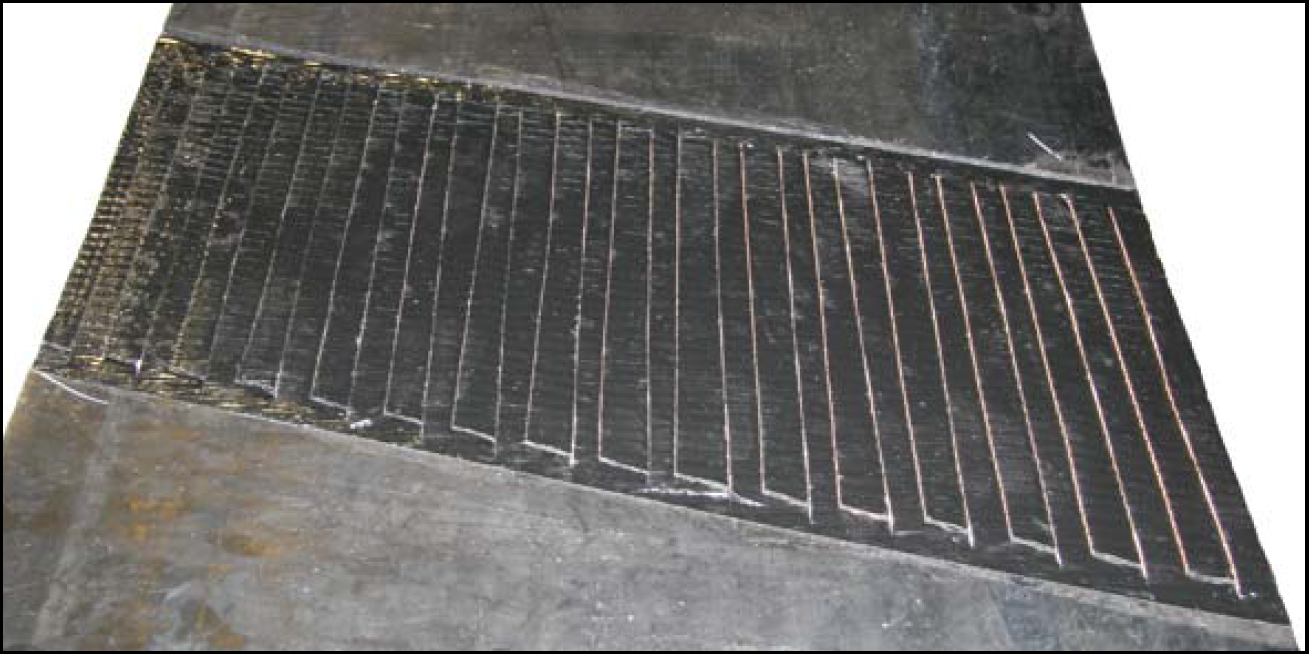
Aim of this procedure is to show the special fabric interweaving; for this reason, the base method for rubber belt joining is expected to be well known, as described in our “Installation manual”, available for our customers in SIG’s web site. Therefore, we do not refer to the classical activities such as the cut of the correct belt length, the solution application on the surfaces to be matched, the fabric cleaning, the cover rebuilding, the heads alignment, the vulcanization.
- Eliminate the covers of both the belt heads for a length equal to L+25 mm;
- Apply a layer of skim rubber 0,5 mm thick on the 4 fabric faces;
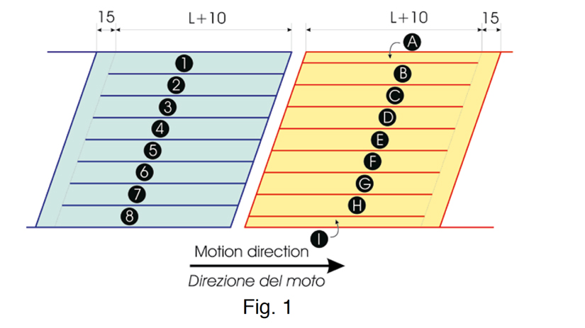
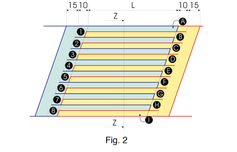
- Mark the cutting lines of width S following the scheme of Fig. 1, making sure that the narrow extremities (A and I) are opposite to the motion; the last couple of strips (A-1-I-8) must be adapted in width according to the belt width;
- Cut the fabrics along these cutting lines;
- Place the bottom cover with thickness of approximatly 1 mm less than the original one, with a minimum of 2 mm;
- Align the two belt extremities at a distance such as to allow a strip overlapping with length L;
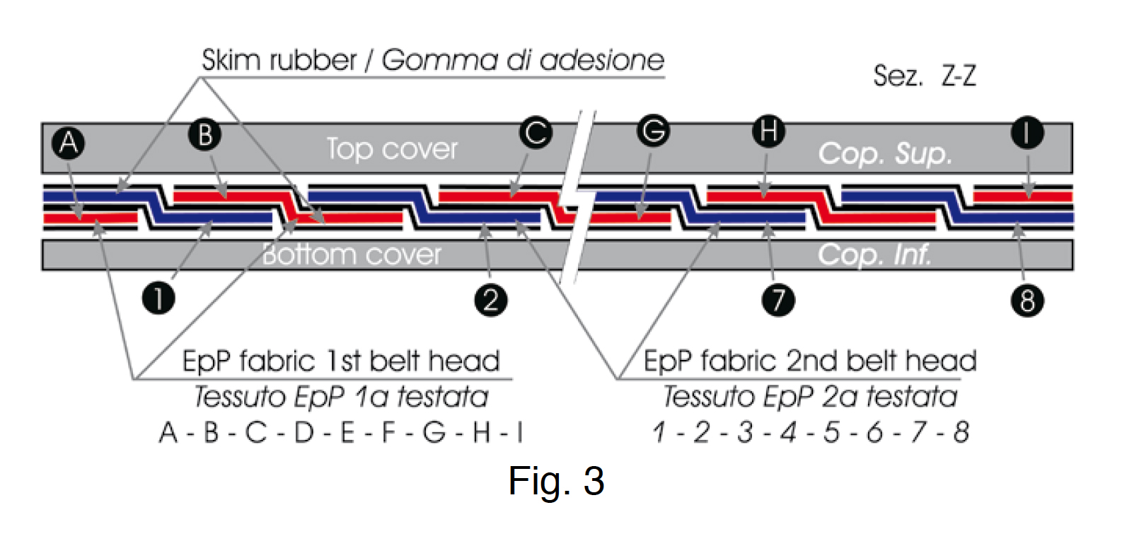
- Following the scheme of Fig. 2 and 3, place the strips on the bottom cover starting from A, alternating the two heads (sequence A–1–B–2–C….7–H–8–I), assuring the alignment and the planarity of the strips themselves; please note that the strip heads must not be positioned at the end of the cut but 10 mm back in order to favour the transversal bending of the fabric;
- Put suitable quantity of uncured rubber to cover all the differences in thickness at the end of the fabric strips;
- Place the top cover over the joint taking in mind that the thickness must be approximately 2 mm less than the original;
- Proceed with the vulcanization.
|
Belt style N/mm |
400 | 630 | 800 | 1000 |
|
Overlapping length L mm |
450 | 750 | 950 | 1250 |
|
Strip width S mm |
50 | 70 | 100 |
100 |
| Length to be prepared L+25 mm | 475 | 775 | 975 |
1275 |
| Total joint length mm | 500 | 800 | 1000 |
1300 |
In case efficiency values lower than 90 % are required, it is possible to reduce the overlapping length L up to a suggested maximum of 20 % (i.e., for class 400, L becomes aprox 350 mm). In this case, the splicing efficiency remains anyway over 70 %. On the contrary, we suggest to increase L of 20 % for high temperature applications.
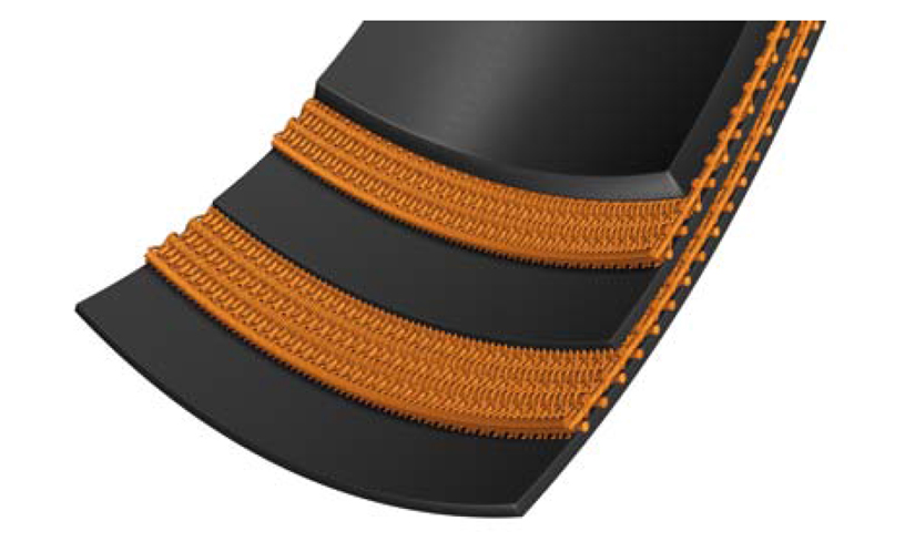
The joint of Texbind double unit can be executed with the typical step methods; as this type of belt is often selected for its solidity and not for the specific guaranteed tensile strength, it is possible to choose 1 or 2 step method according to the desired efficiency: maximum 50% in the first case, up to 90% in the second one.


